I am a student in the Department of Mechanical and Aerospace Engineering
at Cornell University. I am interested in robotics. This webpage contains all of the lab
reports for MAE 5190 Fast Robots.
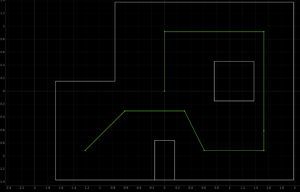
The objective of the lab is to have the robot navigate through the map and reach nine different
points. An image of the map and the location of the nine points (feet) are below.
Lab Tasks
Part 1: Open Loop Control
I initially started working on an open loop control design, before working on localization. My
goal for this section was to determine how far I could get in the map before the robot no longer
reached the goal points. While working on this section I became even more familiar with how the
robot operated. I needed to regularly change the battery as the robot behaved differently depending
on how charged the battery was (moving and turning slower when the battery was not fully charged).
This was important for determining how fast the robot would
approach and stop before the wall and turn. In addition the right side motor of the robot has a
slight delay in reaching the final set speed compared to the left side. This results in the robot
initially moving straight but moving towards the left for longer distances when working with a
fully charged battery. I needed to account for
this factor when determining where to stop and turn the robot. This behaviour can be seen in the
some of the lab report videos. The details for the planning and implementation of the open loop design is below.
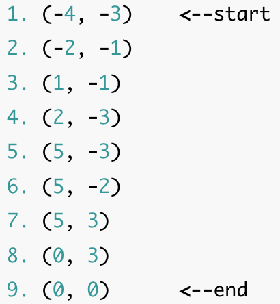
Planning An Initial Design
The above image shows the first design, marking the predicted distances that the robot needed to
travel for each section of the map. While thinking through the first design I was planning on
measuring the initial distance from the robot to the back wall at an angle and then recording
how much the distance changed to stop the robot after around 862mm. I was also going to use the
same approach for travelling from point 3 to point 4. All other distances were going to be measured
from the wall. I decided to change this approach to simplify the design and minimize the room for
errors. Measuring the distance to the wall at an angle could result in the robot stopping to soon
or moving to far if the robot is not oriented to the correct angle when starting or turning. I
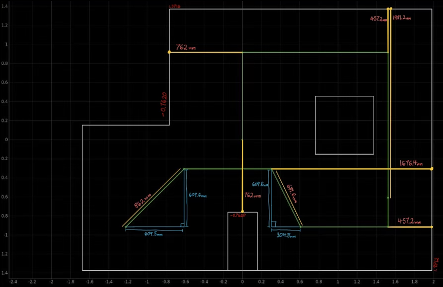
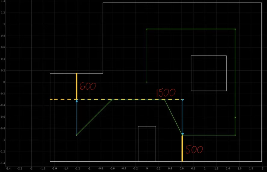
decided to change the design to model the diagram below.
In this design the robot is able to get distance readings from a closer wall that the robot is
directly facing. The robot also is expected to turn 90 degrees every time a rotation needs to be
made, simplifying the code compared to needing to turn at around 45 degrees for two turns and then
turning 90 degrees for the remaining turns. However, while physically testing the robot I did still
need to adjust the angles the robot turned as not all turns worked well using 90 degrees. In the
above diagram are the final used angles and distances for the robot path. The details about the
design implementation are below.
Implement The Design
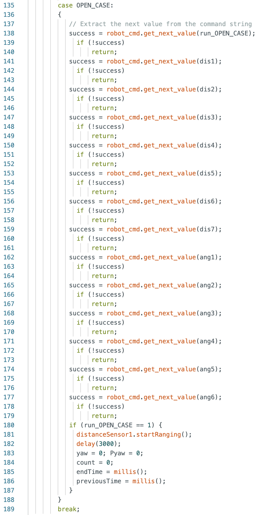
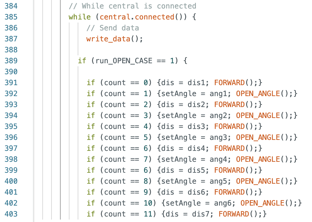
When I started working on the design for the robot's path I wrote the code in sections and tested
the run in parts before writing the next segment. Below is the Jupyter Notebook command and the
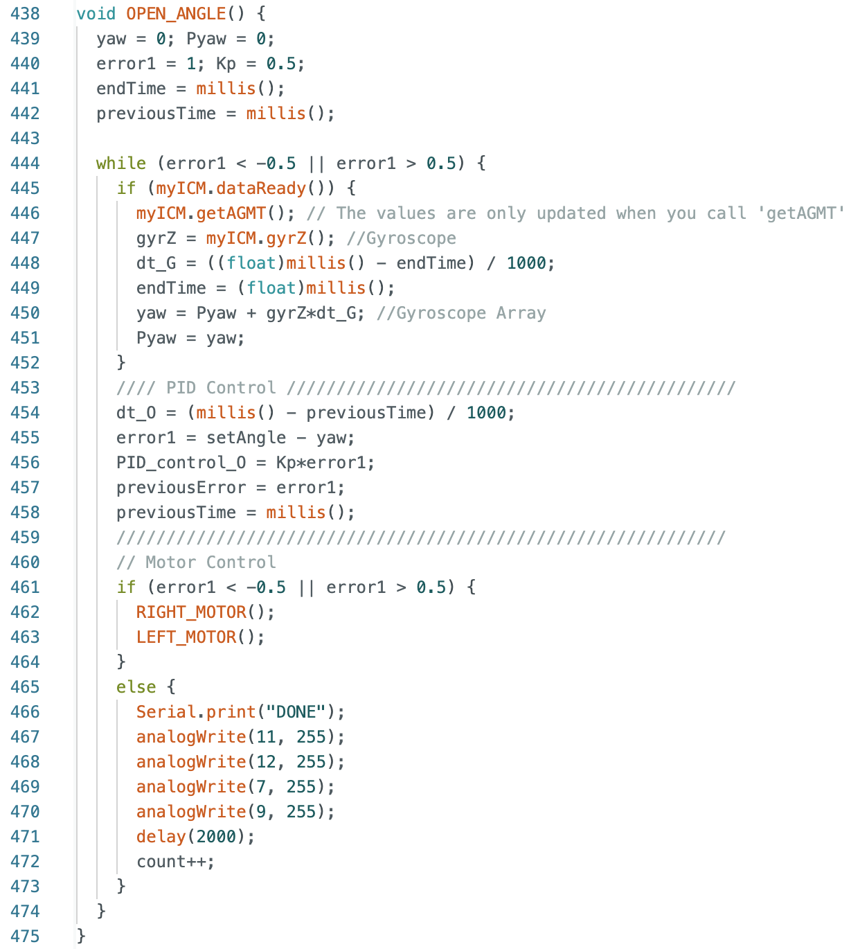
Arduino case, while loop, and functions. Each distance and angle are set separately to allow for
any changes to be easily made during testing. PID control is used when the robot rotates. The
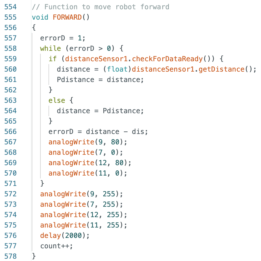
FORWARD function does not use PID control for distance readings as the robot was set to move at
a slower speed of 80 PWM and would not overshooot the desired stopping distance.
Jupyter Notebook Command and Arduino Case:
While Loop:
OPEN_ANGLE and FORWARD Functions:
As I progressed through the map it was harder to reach each point. The most common failure was
missing the second to last point or overshooting the turn at point 5, resulting in the robot
hitting the side of the box.
This folder
has two videos showing errors in the initial design. One video shows the robot not reaching
point 3 because the ToF sensor measured the distance to the box and not the wall. The robot stopped
before passing point 3. This was a frequent error and during testing I adjusted the first stopping
distance and had the first angle be a rotation to -100 degrees. This allowed for more runs to be
successful until the third point, as the ToF sensor did not detect the box and distance was allowed
for the right side motor to slightly move the robot to the left. Unfortunately, this correction
also resulted in another potential error of the robot missing point 3. When the robot had a fully
charged battery, it tended to reach the first three points more frequently than if the battery was
not fully charged due to the right side motor reaching full speed faster when using a fully charged
battery. For this reason during this lab I repeatedly recharged the batteries I was using more often
than in any previous lab. In addition, the turn at point 5 was set to 80 degrees to account for the
right side motor and prevent the robot from hitting the side of the box. The second video in the
folder shows a failed run where the robot misses the second to last point.
Below are two videos of the most successful runs. Due to using open loop control and having an error
tolerance for the angle turns and variations in speed depending on the battery charge, each run was
slightly different. In the first run the robot passes the third point but does not go through the
center. In both runs the robot passes the last point but does not stop until after passing the point
as the robot was not perfectly in line with reading the distance to stop from the smaller box. I was
happy with the results as I had spent a long time working through the nuances of the robot and the
robot is able to make its way through the map.
Run 1:
Run 2:
-->
Part 2: Localization
In addition to doing open loop control, I decided to implement localization on the robot the
details about planning and implementation are found below.
Planning An Initial Design
From my observations while implementing open loop control, I decided to make some changes to the
path of the robot. My plan was to perform localization starting at point 4 and continue to localize
at each point (except point 6 as it occurs right next to point 5 and will be passed on the robots
path to point 7) until the robot completes the map. The robot will initally move using open loop
control until reaching point 4. Instead of rotating clockwise and having the ToF sensor pointed
towards the right side wall, I decided to rotate the robot counter clockwise and have the ToF
sensor pointed towards the left side wall. The robot then moves backwards a specified distance
away from the left wall. I decided to change the open loop control as in the previous section there
were several runs where the ToF sensor read a distance from the large square box and not the right
side wall. Having the ToF sensor read distances from the left wall removes the possible error that
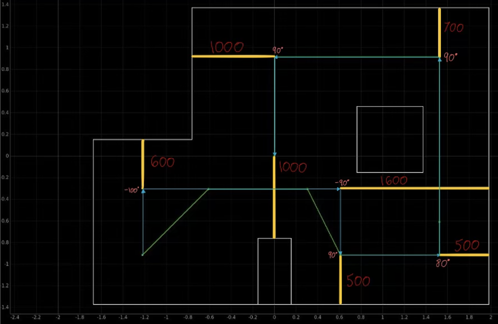
the robot will sense the box and stop early. Below is a diagram of the robots path.
For localizing and moving to the next point I broke down the robots movements into five actions:
Localization on the robot
Compare the localization results with the desired point
Rotate the robot to face the desired point
Drive the robot for a specified distance towards the desired point
Rotate the robot back to face the right side wall for the next localization
The Arduino open loop script and the functions I wrote to control the robot are found below:
Open Loop Control
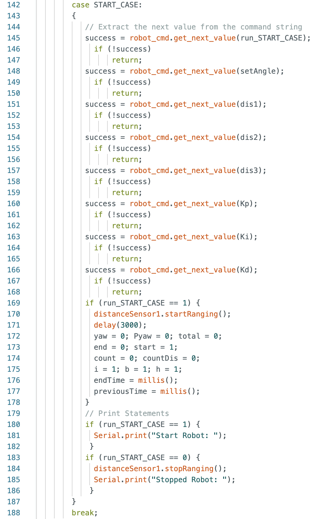
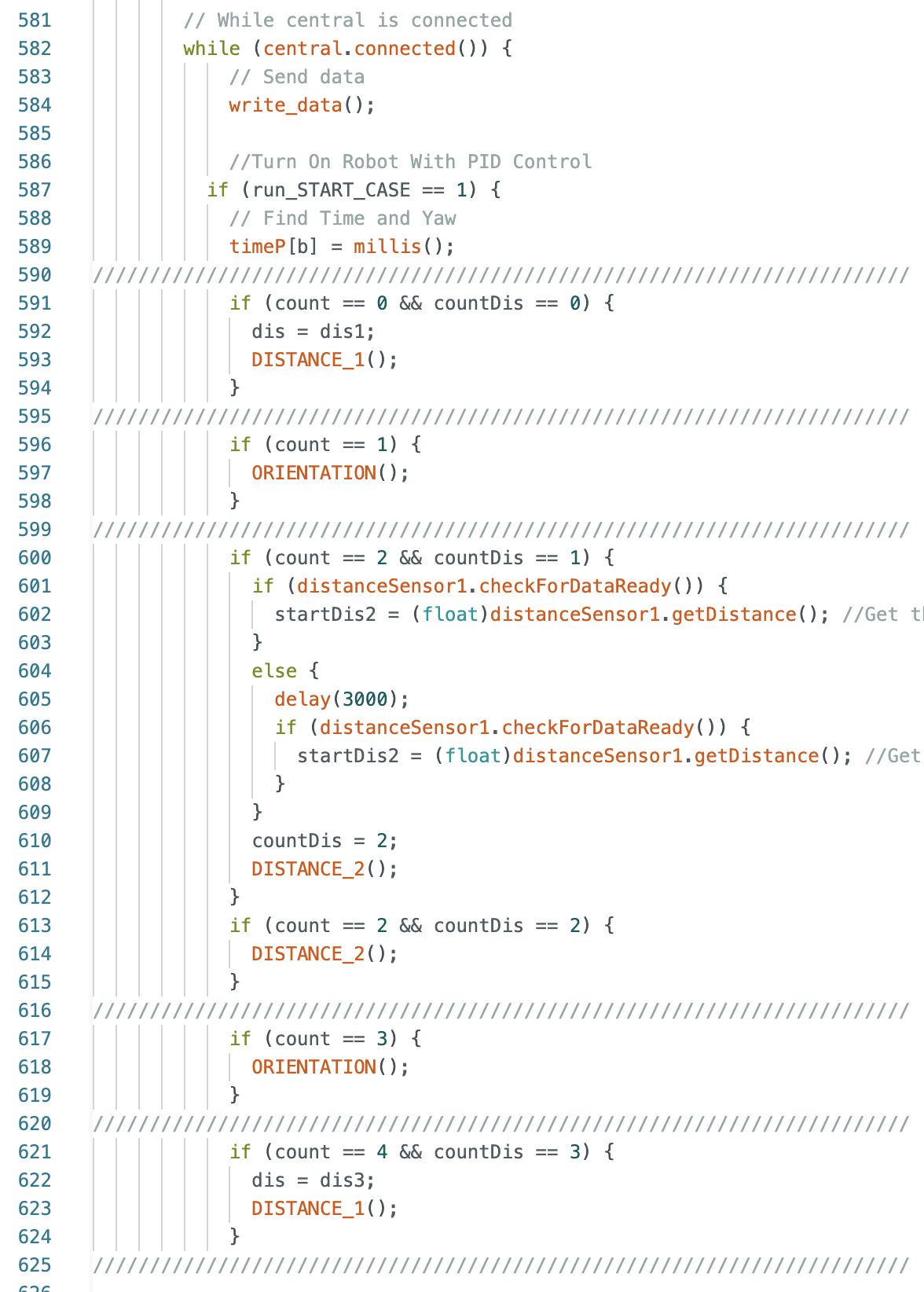
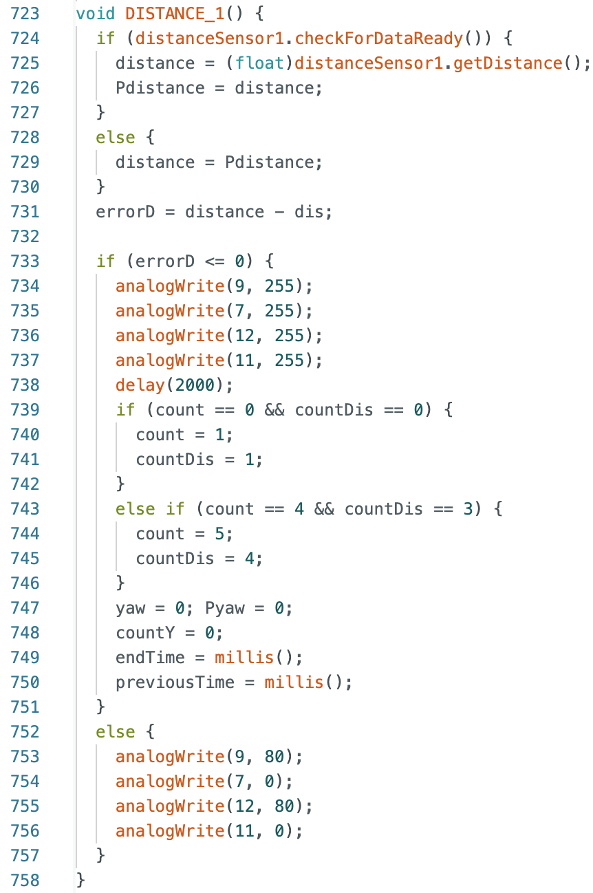
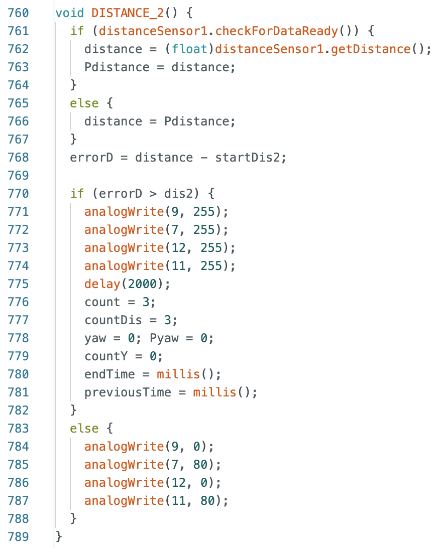
Below is the Arduino case for open loop control and the code within the while loop. When run_START_CASE
is set to 1 the first function entered is DISTANCE_1 and the robot starts moving forward until
stopping 600mm in front of the wall. The robot turns 90 degrees counterclockwise using the
ORIENTATION function and then drives backwards away from the left wall by entering the DISTANCE_2
function. An initial distance reading is taken from the wall and then the robot uses this distance
reading to measure from and move 1500mm. The robot stops just past point 3 and turns 90 degrees
and then drives forward, stopping 500mm before the bottom wall. Within the while loop and each
function are if statements that determine the value of the variables count and countDis. These
values change after each function is run to move onto the next step in the while loop.
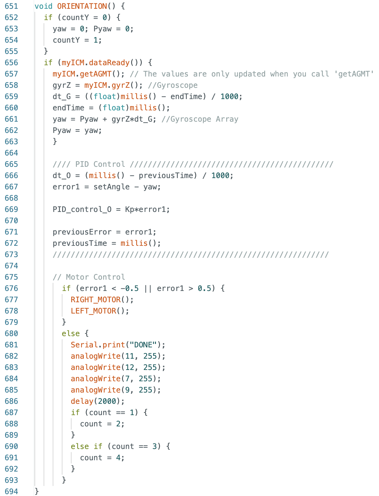
ORIENTATION Function:
DISTANCE_1 and DISTANCE_2 Functions:
After the while loop runs, the case and function below are called to orient the robot towards the
right side wall before starting localization. This allows for the robot to start localizing at
a yaw reading of 0 degrees.
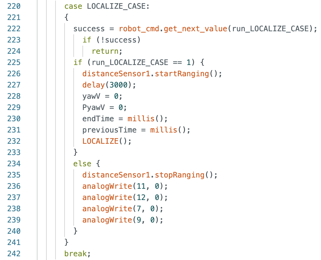
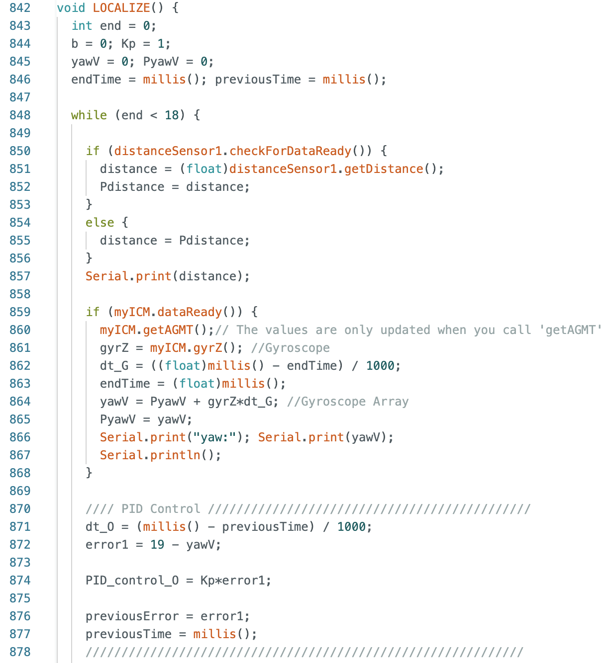
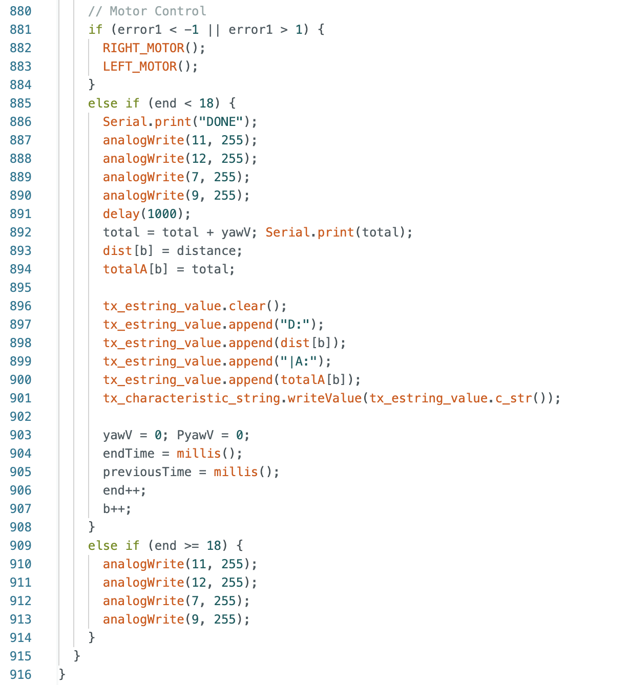
Localization On Robot
Below is the LOCALIZE_CASE in Arduino that calls the function LOCALIZE. The case sets the yaw
reading to zero and records the previous time stamp to be used when finding the next yaw value.
The LOCALIZE function rotates the robot 360 degrees while recording ToF sensor distance measurements.
The robot had a tendency to overshoot the rotation when the goal angle was set to 20 degrees.
I tested various angle changes for a 360 degree rotation and found that increments of 19 degrees
(+/- 1 degree) allowed for the robot to stop the rotation without overshooting. This correction
worked for the first few localization attempts, but as the robot localized more the error in overshoot
increased. This error in rotation is also affected by angle changes to direct the robot to
the desired point in the map as in the function ANGLE described in the next section.
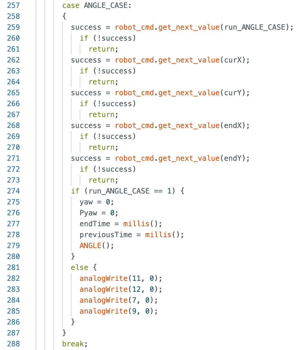
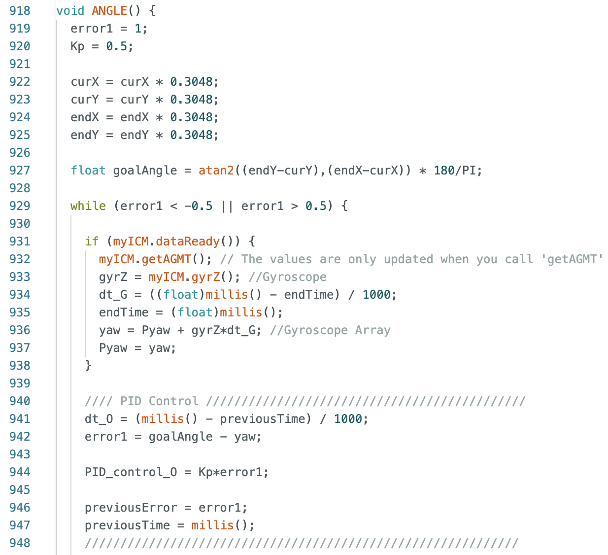
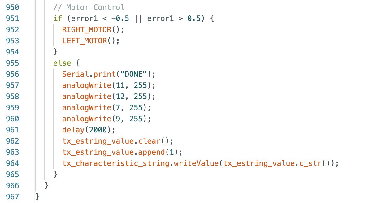
Changing The Angle
The below case and function rotates the robot by the calculated angle. The ANGLE function uses
atan2 to find the rotation angle using the inputs for the current position (curX,curY) and the
desired position (endX,endY). This calculated goalAngle is then compared to the current yaw
reading of the robot until the error is within 1 degree of the desired angle.
I tested the above code for angles of -45, -90, -135, 45, 90, 135, and 180 degrees. All of the
videos can be found in
this folder.
Below are three videos of example rotations. The timing for the serial monitor and the video of
the robot moving do not match because to record the serial monitor output I turned the robot
using my hand rather than using the motors.
90 Degrees:
135 Degrees:
180 Degrees:
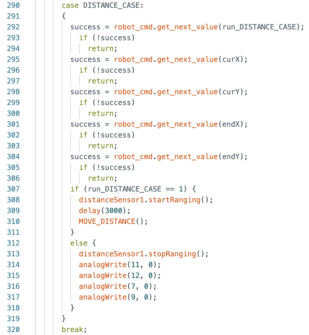
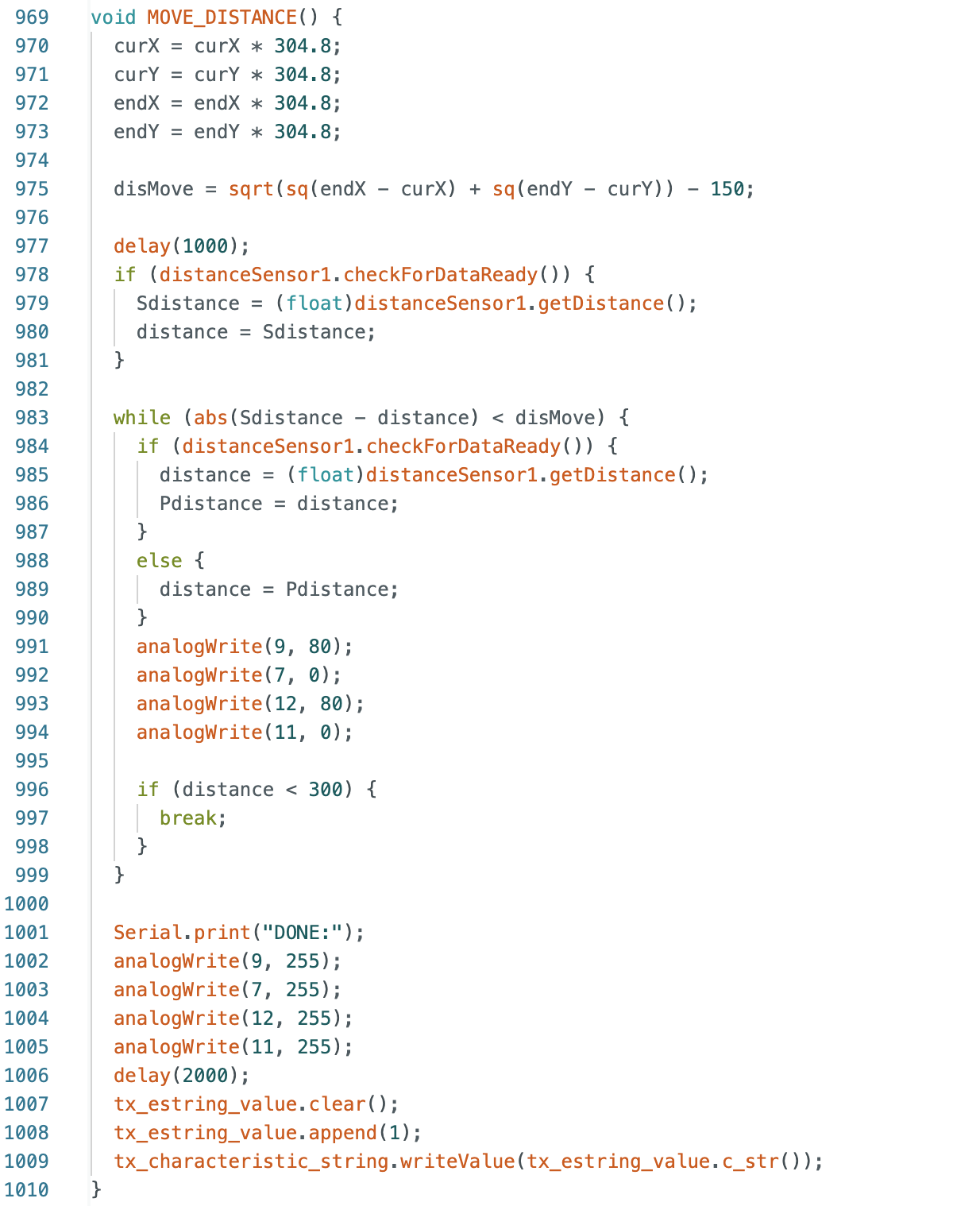
Driving To The Next Point
The next section of code I wrote has the robot move from the current point (curX,curY) to the
desired point (endX,endY). The case and function are below. I also subtracted 150mm from the
calculated value because when I was testing the robot in the map, there was consistently some
overshoot when reaching the desired point due to the belief and desired points being modeled at
the center of the robot and the distance readings coming from the ToF sensor at the front of
the robot. An initial distance reading is taken and then the
current distance reading is subtracted from the starting distance. This value is compared to
the calculated disMove and the robot stops when the difference between the starting and current
distance readings is greater then the value for disMove. In addition, I added a break statement
that exits the while loop if the robot is within 300mm of the wall. This is to prevent the robot
crashing or getting stuck in a corner.
Below are two videos of the robot moving and the serial monitor output changing. These videos
were taken before subtracting 150mm from the calculated distance.
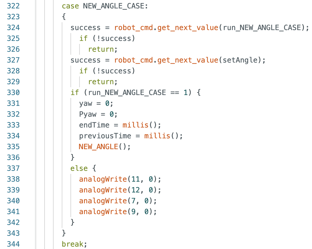
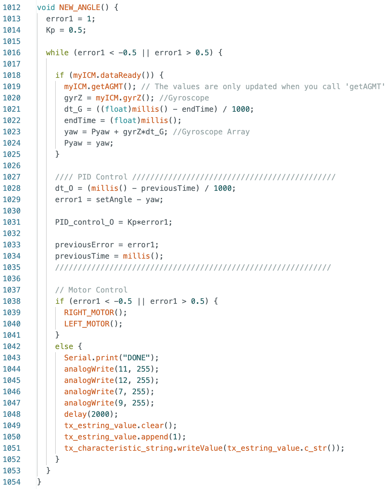
Rotating The Robot For The Next Localization
The last step before the next localization attempt is to rotate the robot again towards the right
side wall. During this step the function NEW_ANGLE is called, using the negative of the same
angle calculated during the "Changing the Angle" step. The function NEW_ANGLE was described
previously in the lab.
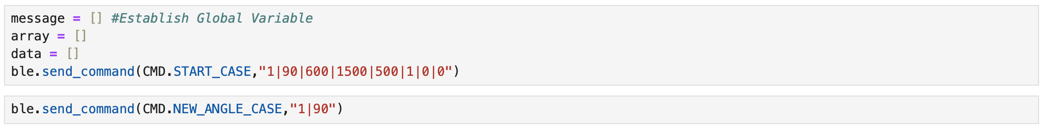
Writing A Python Script
Below is the python script used during the open loop control and localization of the robot.
Step 1: START_CASE is called with inputs for run_START_CASE, setAngle, dis1, dis2, dis3, Kp, Ki,
and Kd. The robot navigates to point 4 before stopping. NEW_ANGLE_CASE is called with inputs for
run_NEW_ANGLE_CASE and setAngle. The robot rotates to face the right side wall.
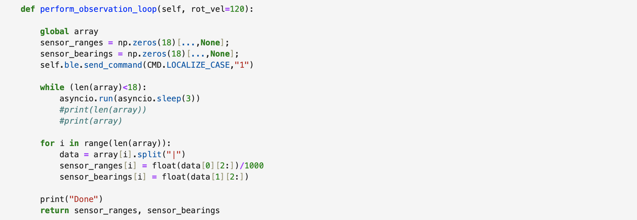
Below is the function perform_observation_loop in Jupyter Notebook that calls the LOCALIZATION_CASE
to rotate the robot and collect ToF data to use in the Bayes Filter.
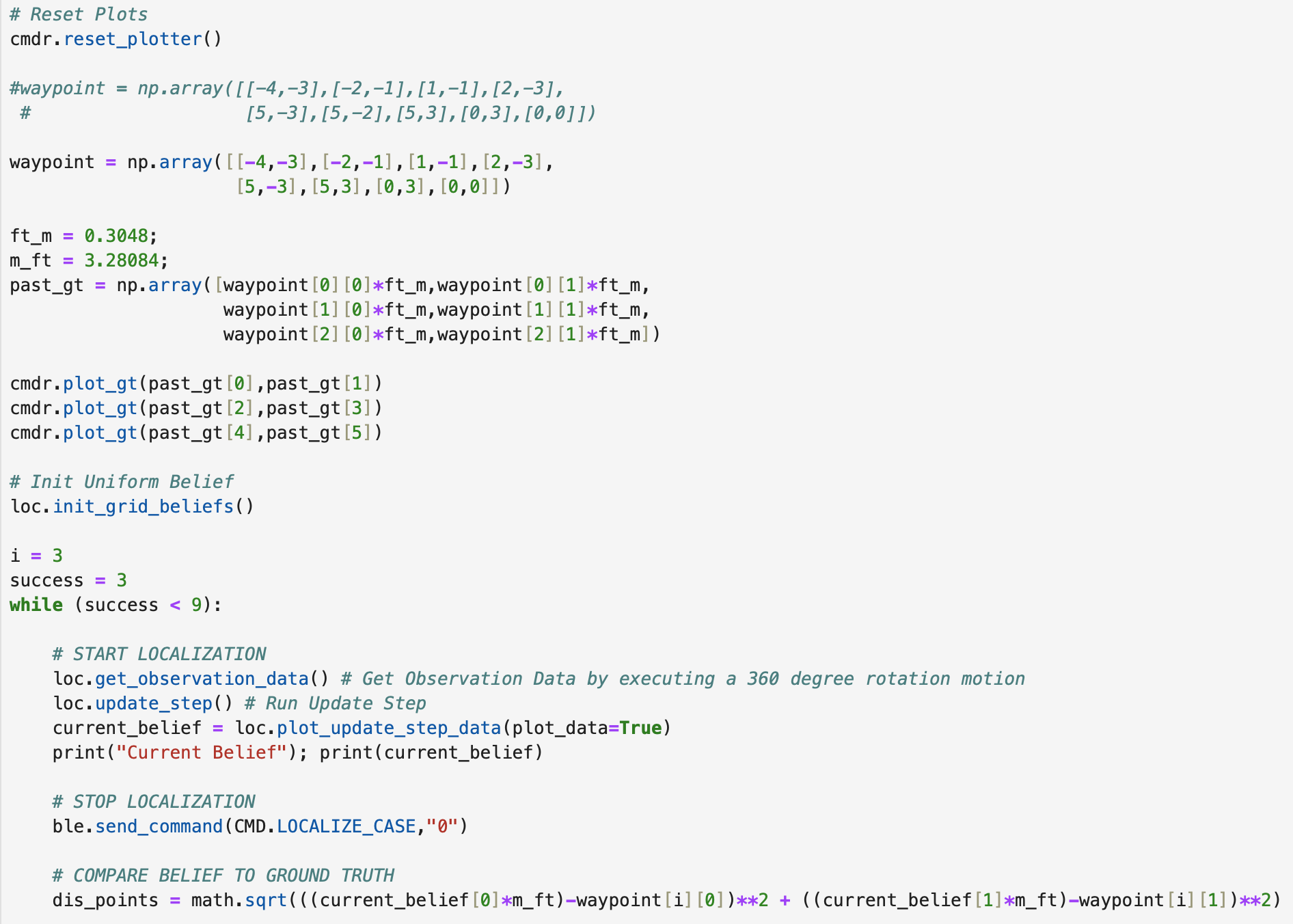
Step 2: During this step the plotter is reset and then points 1, 2, and 3 are plotted on the graph
assuming that the robot has passed all of those points using open loop control. The while loop is
entered and the robot starts localizing. After localizing, LOCALIZE_CASE is turned off and the belief
of where the robot is on the map is compared to the desired point.
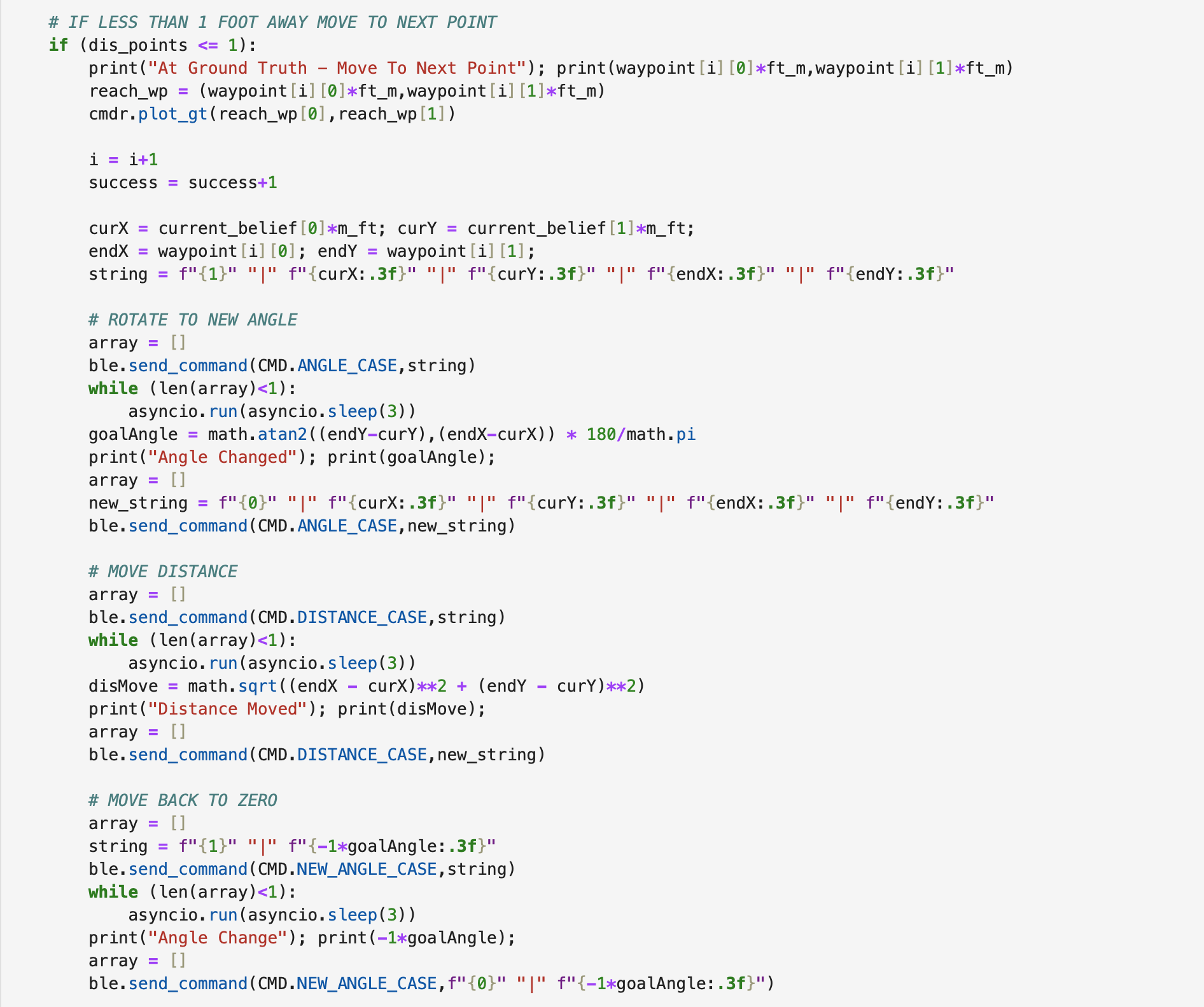
Step 3 (Inside While Loop): An if statement is made to check to see if the belief is within 1 foot
of the desired point.
If the belief is within 1 foot, the ground truth value for the desired point is plotted and the
values for the index i and the success are increased. The x and y coordinates for the current
belief and desired point are assigned to variables (curX,curY) and (endX,endY). A string using
the found point values is created and ANGLE_CASE is called to rotate the robot to face the next
desired point. After the robot rotates the case is turned off. Then the DISTANCE_CASE is called
using the same inputs and the robot travels to the next point. After moving the desired distance,
the case is turned off. Finally, the robot uses the negative of the angle found during the "Rotate
to new angle" step as an input to the NEW_ANGLE_CASE to rotate towards the right side wall and then
the case is turned off when the robot stops.
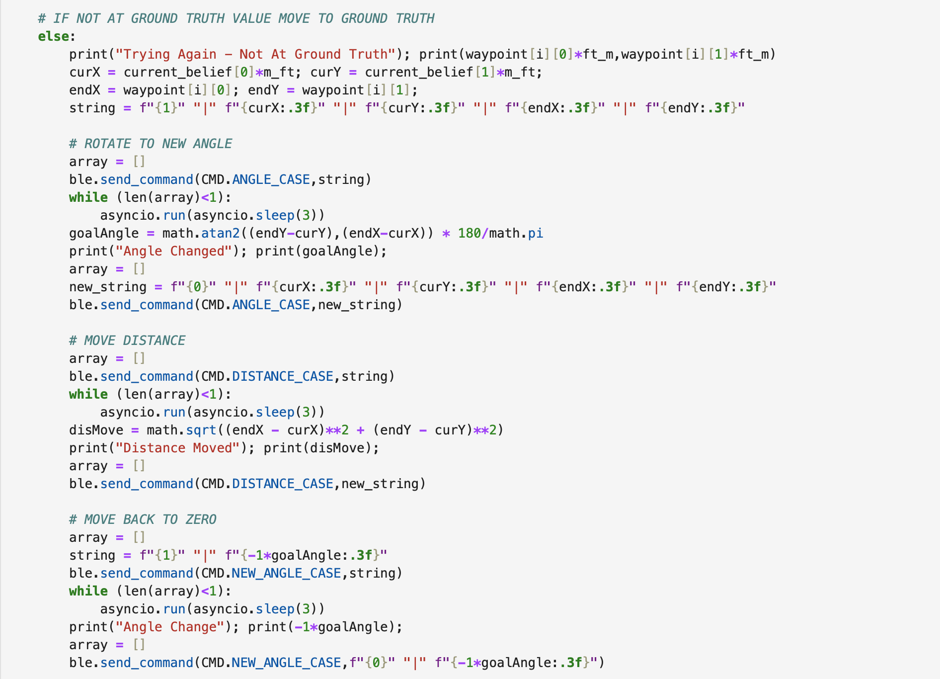
Step 4 (Inside While Loop): The else statement runs if the belief is not within 1 foot of the
desired point. All of
the previously run cases are used in the same manner, except the index and success variables are
not increased. The robot is still trying to reach the desired waypoint.
Testing The Robot In The Map
Below are videos and graphs of various tests.
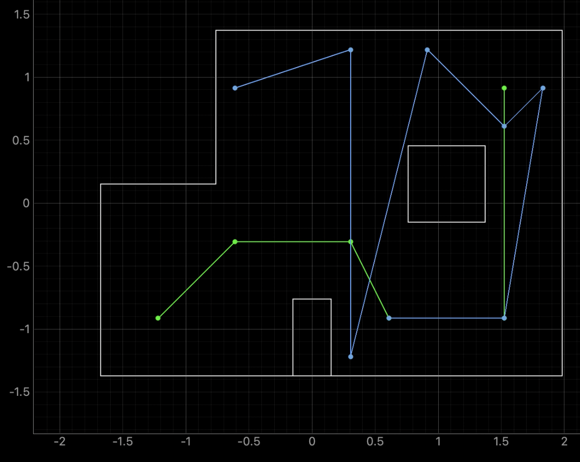
Localization Starting At Point 4:
The best localization attempt occurred during testing
when I started the robot at point 4. In the video the robot is able to localize around points 4, 5,
and 7, (passing point 6 on its way to point 7). The robot also eventually passes points 8 and 9 but
is not able to achieve good localization results at those locations. In the video it can be seen that
the more localization attempts are run the more error accumulates in the direction the robot faces
before starting the next localization attempt. When the robot reached points 8 and 9 the ToF sensor
was no longer pointed directly towards the right side wall resulting in poor distance data when
running the Bayes Filter.
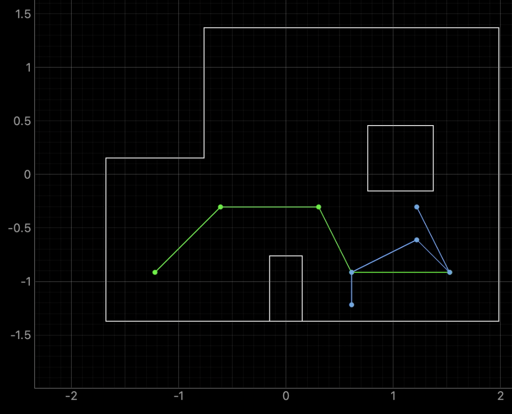
The below video shows another attempt at running the full course as it can be seen the robot
passes the first three points before being rotated and starting localization. The robot got stuck
in the right bottom corner during this attempt. I ran the robot several times using localization and
the most common reason for an unsuccessful run was due to the robot not localizing around point 5.
Overall, I am happy with the results I was able to achieve. The robot was able to localize well within
the general area that it was located. The only exception was for the second to last point in the first
video where localization believed the robot was located near the bottom wall of the map.
There was a lot of planning and testing
during the lab and a lot of code was written for the robot to move as expected. It was very exciting
to see the robot navigate through the map and I enjoyed working on this task for the final lab report.
Thank you!
Below are the RIGHT_MOTOR and LEFT_MOTOR functions used for orientation PID control that were
referenced in some of the previous functions.
I also wrote a function BACKWARD to move the robot backwards but did not use it.
Lab 12 References
I did not collaborate with any students on the lab.
Thank you for a great semester! I really enjoyed working on the labs in this course and I appreciate
the large number of office hours available for students. Have a nice summer.
Thank you to all of the TAs that answered my questions. I referenced the past lab reports of
Liam Kain, Rafael Gottlieb, Larry Lu, Julian Prieto, and Ignacio Romo.